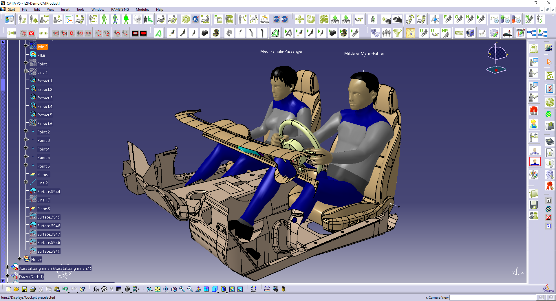
Steps involved in Reverse Engineering

Reverse Engineering: From construction steps to final output
During the reverse engineering process, we need to generate the CAD file in the software best suited for each task. During this process, we should work regularly inside the program and save the construction history of all the steps we take. You can access that history as part of the ready data. Following are the guidelines set by experts in the industry Reverse Engineering Service. If you want to be flawless in the reverse engineering process, you must follow these instructions.
Reverse Engineering with Parametric features
While doing reverse engineering manually, we are able to generate parametric features wherever useful. These features can be used on parts with regular geometry in every CAD software.
Parametric features are very beneficial when working with CAD files.
The data sources we generally work with:
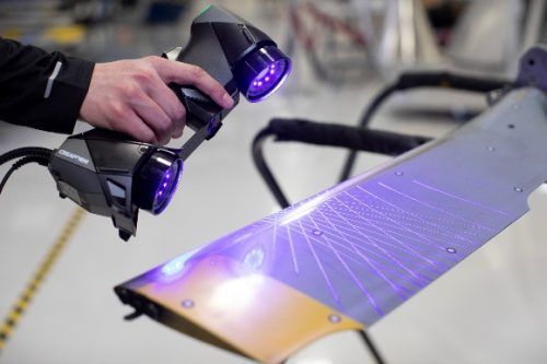
- 3D scans – for example clay models, as explained in the sample above
- Simulations – FEM, ANSYS or material flow in moulds (Cadmould / Moldflow)
- Optimizations – product tolerance optimization (GOM inspect Pro)
Reverse Engineering from 3D Scan
When working with 3D scan data, we must follow these steps to remodel into parametric CAD data:
- Make an impression on paper
- Build detailed units of the model
- Modify the units until they fit on the pointcloud
- Add parametric features to the units
- Remodel the units some more
- Continue adding parametric features
- Compare pointcloud and cad data regularly to ensure fit
- Assemble the parts together
- Double check to ensure tolerances between STL and CAD data are below requested figures.
If tolerances are not reached, the engineer will modify the structure into smaller elements and go back to step 5 of above list, until his reverse engineering arrives at the required tolerance.
Reverse Engineering of simulation data
Pointclouds in this case, are a result of simulations done with original straight and clean CAD data. Each simulation affects the structure of the original file. As a result, we would need to rebuild many free forms faces and implement the models into the original CAD software.
The general steps followed when creating native CAD data from Pointclouds based on simulation data include:
- Check original CAD and pointcloud after simulation
- Identify geometrical parts and free form faces
- Rebuild first geometrical units of the model
- Modify the units until they fit on the pointcloud
- Rebuild free form areas and implement them into the geometrical base
- Continue remodeling the units further
- Compare pointcloud and CAD data regularly to ensure allowable tolerances
- Assemble all the parts together.
- Ensure requested tolerance between simulation file and CAD data are below requested figures
If tolerances can‘t be reached on the first attempt, the engineer will modify the structure into smaller elements and progress from step 5 of the above list, until the target tolerance is reached.
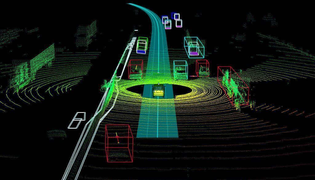
Reverse Engineering of pointcloud
Large objects can be complicated to scan and duplicate.
When reading the surface of a large object, the error margin can be huge and, the scanner might pick damage or dirt that’s on the surface.
Hence point clouds. Pointclouds are coordinates in space that represent a scanned object. After scanning, the points are then put together to create CAD data.
Below is the process we should follow when reverse engineering generated Pointclouds:
- Checking original CAD and pointcloud after 3D scan
- Generate average pointcloud file out of 5 test parts
- Rebuild geometrical units of the model
- Modify the units until they fit on the pointcloud
- Remodel free form areas and fix them into the geometrical base
- Continue with further units
- Compare data base and cad model regularly to ensure tolerances are reached
- Assemble all faces together.
- Ensure tolerance between simulation file and CAD data are below the tolerance that the customer is asking for.
It is standard practice to cut the CAD structure when dealing with large file sizes. The different parts are then combined to form the original geometry.


Comments
Post a Comment
Thank you for your message! We value your feedback!